Table of Contents
ToggleWhat is RTD?
Hello everyone, welcome to another blog of Instrumentation. In this blog we will discuss what is an RTD and how it works in temperature measurements.
The term RTD stands for Resistance Temperature Detector.
RTD is a temperature sensor that is used to measure temperature by associating the resistance of the RTD element with temperature. When RTD is a passive device, external electronic devices are used to measure the resistance of the sensor by passing a small electrical current through the sensor. Working Principle Every material has atoms in it and all atoms have some energy due to which it vibrates slightly.
When a battery is connected to a conductor, current flows through the conductor. Since the flow of current is due to the flow of electrons, these electrons frequently collide with vibrating atoms of the conductor. These collisions decrease the speed of the electrons. This property of a material due to which it opposes the flow of current through it is called resistance.
Now when we heat the conductor, the atoms of the conductor absorbs heat energy as a result their vibration increases. Because of this increase in vibration, the collision of electrons with atoms also increases and so it becomes very difficult for electrons to move across the conductor and hence the resulting output current decreases.
An RTD works on this principle of measurement which states that the resistance of a material changes with temperature. As the temperature of the metal increases, the metal’s resistance to the flow of electricity also increases.
Parts of RTD
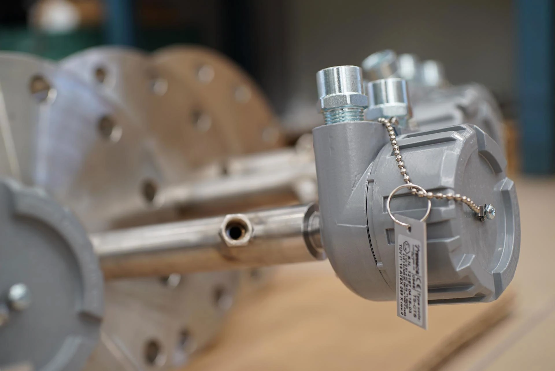
1) Sensing Element or RTD Element: The sensing element is the actual temperature sensing unit which is located at the tip of the temperature sensor on the end that is exposed to the process temperature. The sensing element which is constructed of metals like platinum, nickel, copper or tungsten respond to the process temperature by generating a measurable resistance.
2) Lead wires: Lead wires are attached to the sensing element and then pass through the sensor sheet. Lead wires connect the sensing element either directly to the DCS or to a temperature transmitter connected to a DCS.
3) Sensor sheet: The sensor sheet is constructed of metal and holes most of the competent parts of the temperature sensor. The sensor packing typically magnesium oxide surrounds the sensing element and is contained within the sensor sheet. The sensor packing decreases the impact of process vibration on the sensing element and thus ensures a more accurate measurement.
4) Threaded Adapter: The threaded adapter is welded over the rear housing of the sensor sheet. The magnet of the threaded adapter threads into a thermal weld or directly into the process piping. The other end is typically threaded into a temperature transmitter.
Working of RTD
Suppose we want to monitor the temperature of an oven. To do this work the probe of an RTD is inserted into the oven. Due to the temperature of the oven the resistance of the sensing element of the RTD varies correspondingly.
The RTD gives output of resistance in ohms but that is not a standard signal that can be transmitted into the control room. So we have to convert that change in resistance to a change in voltage and this can be done using Wheatstone bridge.
These Wheatstone bridge circuits are built into the transmitter PLC, DCS or PID controller.
RTD may be located hundreds of feet away from the bridge circuit.
Two types of Wheatstone bridge circuit configurations are mainly used. One is Null balanced bridge and the other is Deflection bridge.
1)Null balanced bridge: In this the resistors are 1 and are 2 are known and are 3 is an adjustable resistor. The resistor are 3 is initially adjusted in order to obtain 0 volt in the voltmeter. In this condition the bridge is said to be Null balanced. This would be the zero or set point on the RTD temperature output. As the RTD is inserted into the oven the RTD temperature increases and correspondingly the voltage indicated by the voltmeter also increases.
2) Deflection bridge: In this all 3 resistors are fixed and not adjusted and the output voltage varies corresponding to the temperature of RTD. If a voltage transducer replaces the voltmeter a 40 to 20 milli ampere signal which is proportional to the temperature range can be generated.

