
Thermocouples and RTD: Introduction
Thermocouple and RTD are two of the most widely used temperature sensors in industrial and laboratory applications. Both devices convert temperature into an electrical signal, but they work on different principles and are suitable for different environments. Understanding the basics of thermocouple and RTD helps engineers, technicians, and students choose the right sensor for accuracy, range, and response time. In this article, we’ll explore how these sensors work, their differences, advantages, and the best practices for using them in process measurement.
Basics of Thermocouple and RTD
Thermocouples
What are Thermocouples?
Thermocouples are sensors used to measure temperature.
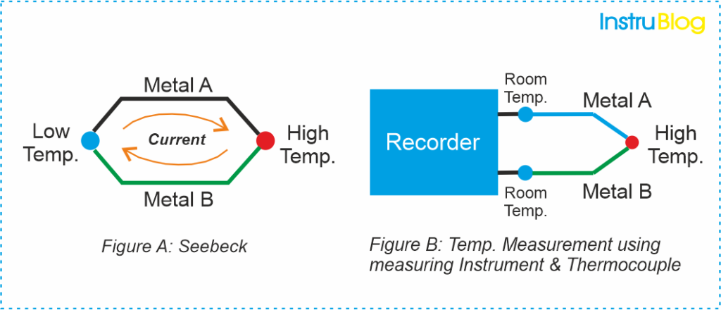
They work based on the principle that when two different metals are joined together to form a closed circuit, a detectable voltage, known as electromotive force, is generated when there is a temperature difference between the two ends of the thermocouple (Please refer – Figure A).
Due to their simple construction and high reliability, thermocouples have found extensive use as temperature sensors in various industrial applications.
By connecting a measuring instrument such as recorders, DCS (Distributed Control System), or PLC (Programmable Logic Controller) to one end of the circuit, it becomes possible to measure the potential difference or electromotive force (Please refer – Figure B).
A variety of thermocouples exist in the market to measure different temperature ranges.
The JIS, IEC standards, and other regulatory bodies have established standardized types that are widely used.
Features, Advantages and Disadvantages of Thermocouples
The following provides an overview of the common thermocouple types (typically represented by symbols) along with their respective features, including advantages and disadvantages.
| Thermocouple Type | Symbol | Features | Advantages | Disadvantages |
|---|---|---|---|---|
| Type K | K | Wide temperature range (-200°C to +1372°C), high accuracy, inexpensive | Versatile, suitable for general-purpose applications | Limited lifespan in oxidizing atmospheres |
| Type J | J | Good accuracy, wide temperature range (-210°C to +1200°C), resistant to oxidation | Suitable for vacuum and reducing atmospheres | Limited resistance to high temperatures |
| Type T | T | Wide temperature range (-200°C to +400°C), high accuracy, immune to electromagnetic interference | Suitable for cryogenic applications | Limited temperature range compared to other types |
| Type E | E | High sensitivity, wide temperature range (-200°C to +900°C), resistant to corrosion | Suitable for high-temperature applications involving reducing or oxidizing atmospheres | Limited resistance to contamination and vibration |
| Type N | N | Wide temperature range (-200°C to +1300°C), high stability, resistant to oxidation | Suitable for high-temperature applications, similar to Type K | Limited availability and higher cost |
| Type R | R | High temperature range (0°C to +1600°C), high accuracy, resistant to oxidation | Suitable for high-temperature applications, excellent stability | Limited sensitivity, expensive |
| Type S | S | High temperature range (0°C to +1600°C), high accuracy, resistant to oxidation | Suitable for high-temperature applications, excellent stability | Limited sensitivity, expensive |
Please note that this table provides a general overview.
When choosing a thermocouple type, it is highly recommended to take into account the specific requirements of your application.
A thermocouple consists of two junctions formed by joining at least two different metals together.
One junction, known as the hot or measuring junction, is connected to the body whose temperature needs to be measured.
The other junction, referred to as the cold or reference junction, is connected to a body with a known temperature.
As a result, the thermocouple measures the temperature of the unknown body relative to the known temperature of the reference body.
Working Principle of Thermocouples
The working principle of a thermocouple is based on three fundamental effects discovered by Seebeck, Peltier, and Thomson. These effects are as follows:
Seebeck effect:
The Seebeck effect explains that when two dissimilar metals are connected at two junctions, an electromotive force (emf) is produced. This emf varies depending on the specific combination of metals used in the thermocouple.
Peltier effect:
As per the Peltier effect, when two dissimilar metals are joined together to form two junctions, emf is generated within the circuit due to the different temperatures of the two junctions of the circuit.
Thomson effect:
The Thomson effect states that when two dissimilar metals are connected, forming two junctions, a potential difference arises within the circuit due to a temperature gradient along the entire length of the conductors.
However, in many cases, the potential difference suggested by the Thomson effect is negligible and can be disregarded by carefully selecting the appropriate metals for the thermocouple.
Thermocouple: How it Works?
The circuit diagram illustrating the working of a thermocouple is depicted in the figure.
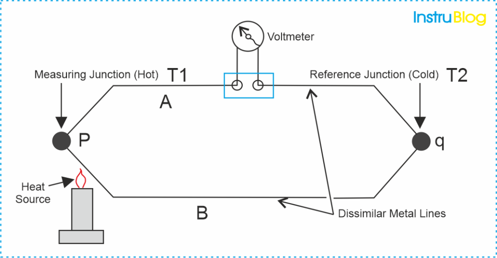
It consists of two dissimilar metals, A and B, connected to form two junctions labeled as P and Q. These junctions are maintained at different temperatures, T1 and T2, respectively.
It is essential to have two junctions for the thermocouple to function effectively. Due to the temperature difference between the two junctions, the Peltier electromotive force (emf) is generated within the circuit. This Peltier emf is dependent on the temperatures of the two junctions.
When both junctions of the thermocouple are at the same temperature, equal and opposite electromotive forces (emf) are generated at each junction. As a result, the net current flowing through the junction is zero.
However, when the junctions are maintained at different temperatures, the emf’s at each junction do not cancel out, leading to a nonzero net current flowing through the circuit. The magnitude of the total emf flowing through the circuit depends on the specific metals used in the thermocouple and the temperature difference between the two junctions.
To measure the total emf or the current flowing through the circuit, suitable devices or instruments can be employed. These devices provide an easy means to quantify the electrical output of the thermocouple.
The device for measuring the current or electromotive force (emf) is connected within the circuit of the thermocouple.
It measures the quantity of electromotive force (emf) that flows through it. This emf is generated by the two junctions of the thermocouple, where two dissimilar metals meet, and are maintained at different temperatures.
The two junctions of the thermocouple and the potentiometer – a device used for measurement of emf are shown.
In the circuit, the temperature of the reference junctions is already known, whereas the temperature of the measuring junction remains unknown.
The output obtained from the thermocouple circuit is calibrated to directly against the unknown temperature.
Therefore, the voltage or current output obtained from the thermocouple circuit provides a direct measurement of the unknown temperature.
Resistance Temperature Detectors (RTD)
What are Resistance Temperature Detectors?
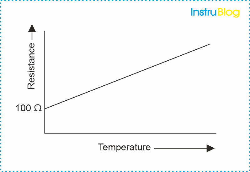
Resistance Temperature Detectors (RTDs) are temperature sensors that operate based on the principle of the change in electrical resistance with temperature. RTDs are typically made of pure metals or alloys with a well-defined and predictable resistance-temperature relationship.
The most commonly used material for RTDs is platinum due to its stability, accuracy, and wide temperature range. However, other materials such as nickel and copper can also be used. The resistance of an RTD increases linearly with temperature, providing a reliable and predictable relationship.
RTDs offer several advantages, including high accuracy, repeatability, and stability over a wide temperature range. They are commonly used in applications where precise temperature measurement is required, such as industrial process control, automotive systems, HVAC (Heating, Ventilation, and Air Conditioning), and scientific research.
To measure temperature using an RTD, a known current is passed through the sensor, and the resulting voltage drop is measured. By comparing the resistance of the RTD with a calibrated temperature-resistance curve, the corresponding temperature can be accurately determined.
I hope you understood what is the difference between thermocouple and RTD.
I hope you like above blog. There is no cost associated in sharing the article in your social media. Thanks for reading!! Happy Learning!!