
Operating Principle of RTDs:
Resistance Temperature Detectors (RTDs) are devices used to measure temperature. They work because certain metals, especially platinum, change their electrical resistance as the temperature changes. To measure temperature, RTDs are used with a current source, and the change in resistance affects the current, which can then be measured.
The accuracy of RTD readings can vary depending on the number of wires connected to the sensor. RTDs can have 2, 3, or 4 wires, and each type has its own features. In this article, we will compare these different types in detail.
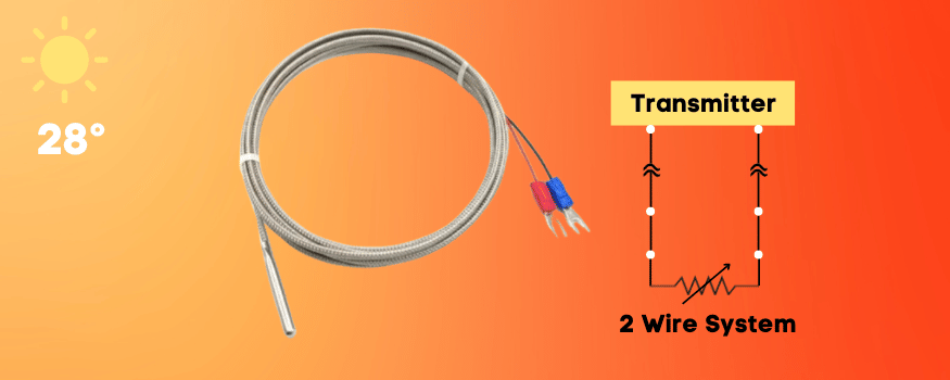
2-Wire RTDs
These are the simplest RTDs to use and set up:
- Connection: Connect the RTD to your measuring device (like a digital multimeter or an RTD reader) using two wires.
- Measurement: Pass a small current through the RTD and measure the resulting voltage. Using Ohm’s Law (V = IR), you can determine the RTD’s resistance.
- Temperature Calculation: With the resistance value, you can find the temperature using the RTD’s resistance-temperature chart.
However, this simple setup has some drawbacks:
Lead Wire Resistance: The wires connecting the RTD to the instrument add their own resistance. For example, if each wire has a resistance of 0.5 ohms, you are measuring an extra 1 ohm (0.5 ohms per wire). So, if your RTD reads 101 ohms, the actual RTD resistance might be only 100 ohms, with the extra 1 ohm from the wires.
Why is this an issue? Even a small change in resistance can lead to a significant temperature difference. If you do not account for the wire resistance, your temperature reading can be inaccurate.
In many applications requiring high precision, a 2-wire setup may not be ideal due to this lead resistance problem. That’s why there are 3-wire and 4-wire RTD setups that help correct this. But for situations where slight inaccuracies are acceptable or cost is a concern, a 2-wire RTD can still work well.
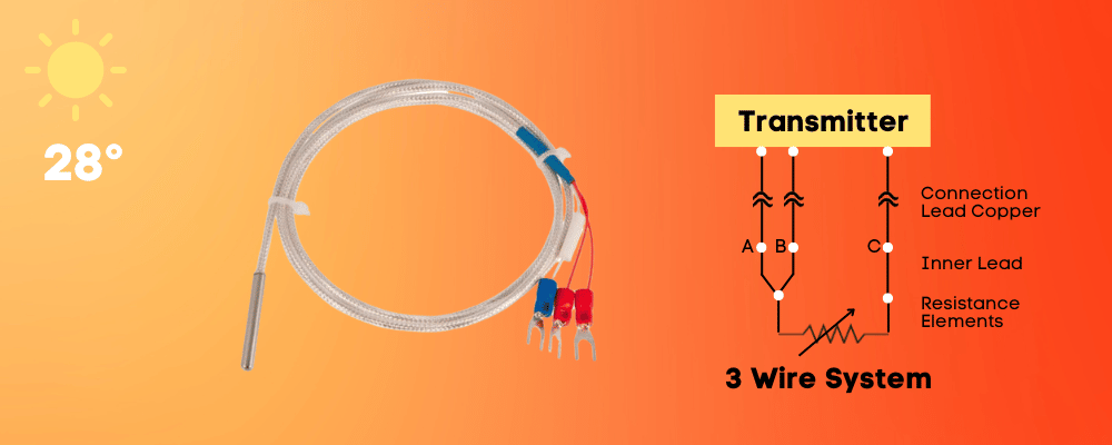
3-Wire RTDs
This RTD type includes an extra wire in the sensor probe:
- Connection: The RTD still has two connection points, but now there are three wires. Two wires (let’s call them A and B) connect to one end of the RTD, and the third wire (let’s call it C) connects to the other end.
- Measurement:
- First, the instrument measures the combined resistance of Wire A, the RTD, and Wire C.
- Then, the instrument measures the resistance of Wire B and Wire C (without including the RTD’s resistance since Wire A and Wire B are connected at one end).
- The instrument subtracts the second reading (B + C) from the first reading (A + RTD + C). This removes the resistance of the lead wires, leaving only the RTD’s resistance.
- Temperature Calculation: Once the accurate resistance of the RTD is determined, the temperature can be calculated using the RTD’s resistance-temperature chart.
Why isn’t it perfect? For the 3-wire setup to work well, Wires A, B, and C should have the same resistance. This means they should be made of the same material, be the same length, and have the same thickness. In reality, there might be slight differences, which can cause minor errors. However, the 3-wire configuration is still much more accurate than the 2-wire setup in most practical situations.
The 3-wire RTD configuration balances accuracy and cost. It provides more accurate temperature measurements than the 2-wire setup by compensating for lead wire resistance, though it might not be as precise as the 4-wire configuration.
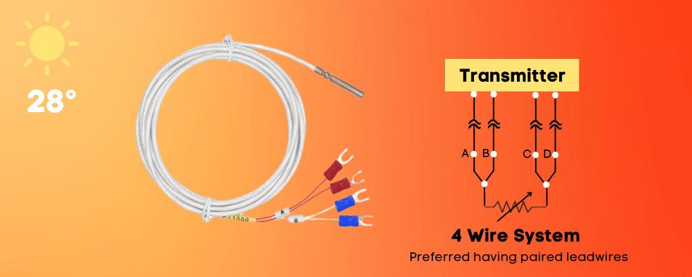
4-Wire RTDs
The 4-wire RTD configuration is designed for maximum accuracy, eliminating the effects of lead wire resistance which can cause errors in temperature readings.
Here’s how the 4-wire RTD setup works:
- Connection: The RTD has two connection points, with four wires attached. Two wires (A and D) drive the current through the RTD, while the other two wires (B and C) measure the voltage across the RTD.
- Principle: This setup separates the current-carrying wires from the voltage-measuring wires to ensure that lead wire resistance doesn’t affect the voltage measurement.
- Measurement:
- Current Drive: A constant current is passed through the RTD using wires A and D. The resistance of these wires doesn’t matter since they’re not used for measuring the voltage.
- Voltage Measurement: The voltage drop across the RTD is measured using wires B and C. These wires don’t carry the current, so their resistance doesn’t impact the voltage reading. The measured voltage reflects only the RTD’s resistance.
- Calculation: Using Ohm’s Law (V = IR), you can calculate the accurate resistance of the RTD, and from this, determine its temperature.
Advantages of the 4-wire system:
- Maximum Accuracy: This setup is the most accurate RTD configuration because it fully compensates for lead wire resistance.
- Consistency: The readings remain accurate even if the lead wires have different resistances due to length or environmental factors.
Considerations:
- Cost and Complexity: The 4-wire system is more expensive and requires more sophisticated instruments compared to 2-wire or 3-wire setups.
- More Wiring: Four wires are needed, which can be a drawback if minimizing wiring is important.
The 4-wire RTD configuration is the best choice when you need the highest accuracy and must eliminate any potential errors from lead wire resistance.
Summary:
Here’s a summary of the differences between the 2-wire, 3-wire, and 4-wire RTD configurations, highlighting their advantages, disadvantages, and best use cases:
2-Wire RTD
Configuration: Uses two wires, one connected to each end of the RTD.
Advantages:
- Simplicity
- Lower cost
Disadvantages:
- Least accurate because the resistance of the lead wires adds directly to the RTD’s resistance, affecting the temperature reading.
Best Used:
- In applications where high accuracy is not crucial
- Where the lead lengths are very short
- Most cost-efficient option
3-Wire RTD
Configuration: Uses three wires. Two are connected to one end of the RTD, and one to the other end.
Advantages:
- Compensates for lead wire resistance, offering better accuracy than the 2-wire system.
How it Works:
- The resistance of two of the lead wires is measured and subtracted out to get the true resistance of the RTD, assuming all three wires have the same resistance.
Disadvantages:
- Not as accurate as the 4-wire system, especially if there are slight differences in the resistance of the three wires.
Best Used:
- In most industrial applications where a balance between accuracy and cost is desired.
4-Wire RTD
Configuration: Uses four wires. Two drive a current through the RTD, and the other two measure the voltage drop across the RTD.
Advantages:
- Provides the highest accuracy by completely eliminating the effects of lead wire resistance on the measurement.
How it Works:
- The current-carrying wires and voltage-measuring wires are separate, so the resistance of the wires doesn’t interfere with the voltage measurement.
Disadvantages:
- More complex
- Can be more expensive due to additional wiring and more sophisticated instrumentation
Best Used:
- In high-precision laboratory and industrial applications where maximum accuracy is essential and cost is not a factor
In Essence:
- 2-Wire: Simple and cost-effective but least accurate.
- 3-Wire: Balances accuracy and cost.
- 4-Wire: Offers the highest accuracy, compensating for all lead wire resistances, but comes at the highest cost.
I hope you like above blog. There is no cost associated in sharing the article in your social media. Thanks for reading!! Happy Learning!!
1 Comment