
More about RTD Sensor Connections
The following illustrations demonstrate the correct wiring connections for all three types of RTD sensors (2-wire, 3-wire, and 4-wire) to a user-configurable transmitter.
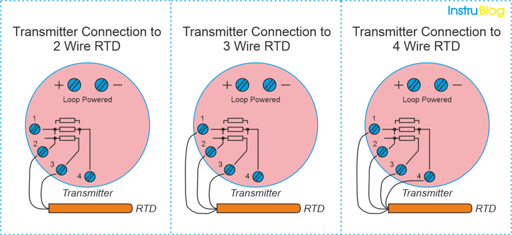
It is crucial to understand that the symbols representing common connections for 3- and 4-wire RTD sensors indicate junction points at the sensor itself, not terminals that are jumpered during installation or internal jumpers within the transmitter.
The purpose of utilizing 3-wire and 4-wire RTD circuits is to eliminate errors caused by voltage drop along the current-carrying wires.
This can only be achieved if the “sensing” wire(s) extend to the RTD and connect directly. If the sensing terminals of the transmitter are only jumpered to a current-carrying terminal, the transmitter will measure both the voltage dropped by the RTD and the voltage dropped by the current-carrying wires, resulting in inaccurate and falsely high temperature readings.
Misconceptions regarding proper RTD connections are unfortunately common, both among students and working industry professionals.
Fortunately, the following presentation aims to address these misconceptions, helping you avoid common mistakes and, more importantly, providing a clear understanding of why correct connections are crucial.
By gaining this knowledge, you will be better equipped to ensure accurate and reliable RTD measurements in your applications.
It is important to always keep in mind the objective of using a 3-wire or 4-wire RTD connection: to eliminate inaccuracies resulting from voltage drops along the current-carrying wires.
This can only be achieved by ensuring that the sensing (non-current-carrying) wire(s) extend from the transmitter terminal(s) directly to the sensor. By doing so, the transmitter is able to effectively bypass the voltage drops in the current-carrying wires and accurately measure the voltage dropped across the RTD itself. This ensures reliable and precise temperature readings.
In the following illustrations, you will find examples of both correct and incorrect methods for connecting a 2-wire RTD to a 3- or 4-wire transmitter.
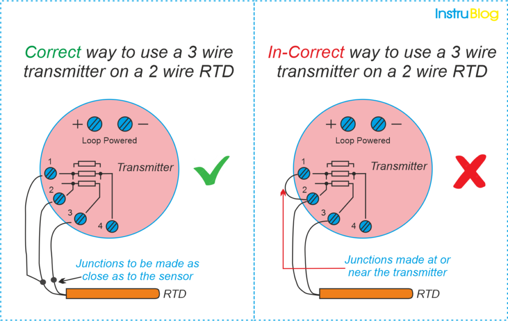
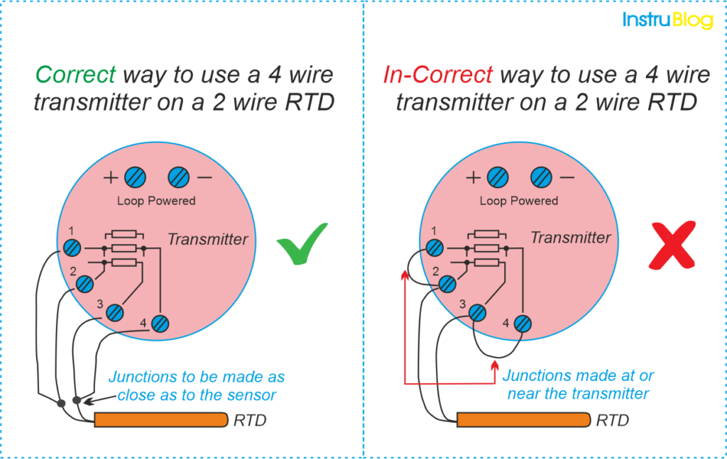
These visuals will help you understand the proper wiring configurations and highlight the potential pitfalls to avoid. It is crucial to ensure the correct connections are made to obtain accurate temperature measurements and prevent any errors or discrepancies.
It is important to note that placing jumpers at the transmitter terminals negates the benefits of using a 3-wire or 4-wire system. This essentially reduces the transmitter’s functionality to that of a 2-wire system.
By avoiding the use of jumpers, you can fully leverage the capabilities of a 3-wire or 4-wire setup, which helps minimize errors and ensures more accurate temperature readings.
A similar issue arises when attempting to connect a 3-wire RTD to a 3-wire transmitter using a readily available 4-wire cable.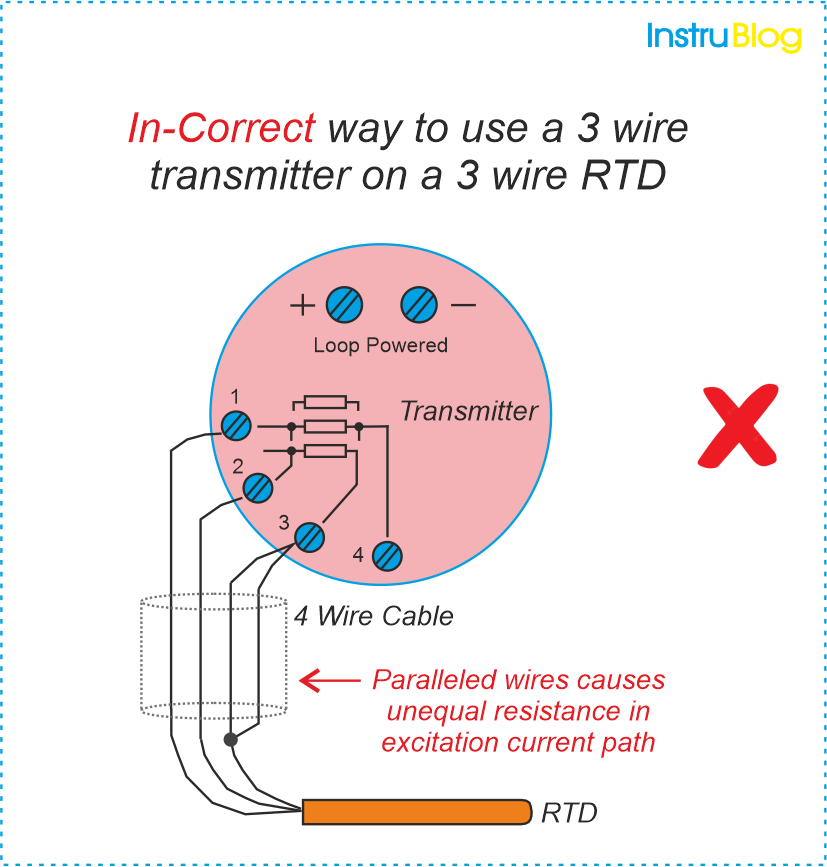
3-wire RTD measurement relies on the assumption that both current-carrying wires possess equal electrical resistance. When you parallel two of the four wires in a 4-wire cable, it introduces uneven resistances in the current path, resulting in measurement inaccuracies at the transmitter.
It is important to note this limitation and avoid using a 4-wire cable for a 3-wire RTD connection to maintain the intended accuracy of the measurement.
Note: The errors will occur only if the paralleled wires carry current. However, if the two wires that have been paralleled happen to connect the transmitter’s sensing terminal to the RTD (the wire that does not carry current), no errors will arise. It is crucial to ensure the correct wiring configuration to avoid measurement inaccuracies in such scenarios.
However, it is important to note that many RTD transmitters do not provide clear documentation indicating which terminals sense (carry no current) and which terminals excite (carry current to the RTD). Therefore, there is a possibility of incorrect wiring if one simply guesses.
Considering that there is no significant advantage in paralleling wires to connect the transmitter’s sensing terminal to the RTD, my recommendation is to either utilize all four wires and configure the transmitter for 4-wire mode, or alternatively, refrain from using the fourth wire altogether. This approach ensures accurate and reliable RTD measurements while avoiding potential wiring errors.
There are two better solutions for the scenario involving a 3-wire RTD and a 4-wire cable.
1. The first solution is to configure the transmitter for 4-wire RTD input and utilize all four terminals. This means connecting the appropriate wires from the RTD to the corresponding terminals on the transmitter, ensuring that the sensing wires are separate from the current-carrying wires.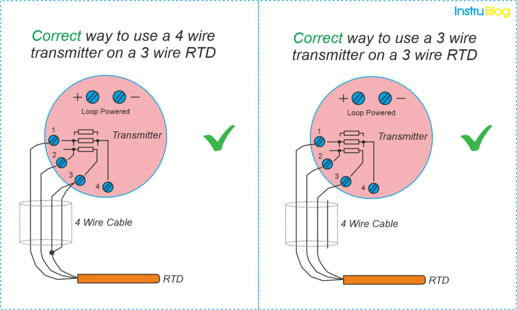
2. The second solution is to keep the transmitter configured for 3-wire RTD input and not use the fourth wire in the cable at all. In this case, only three wires from the cable are connected to the transmitter, again ensuring that the sensing wire is separate from the current-carrying wires.
Both of these solutions ensure accurate RTD measurements and eliminate the possibility of errors caused by incorrect wiring configurations.
RTD Wiring Configurations
There are 3 different types of RTD wiring configurations available which we can be used with the RTD sensing circuit.
2 Wire RTD Configuration
- The 2-wire configuration is the simplest form of RTD wiring setup.
- It involves attaching external leads to the RTD and connecting them directly to the transmitter.
- This configuration is commonly referred to as the serial configuration since there is a serial connection between the RTD and the transmitter at both ends of the RTD leads.
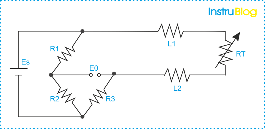
In the provided image, a 2-wire RTD is shown with lead wires L1 and L2 connected in a Wheatstone bridge configuration. - Es represents the supply voltage, while E0 represents the output voltage. R1, R2, and R3 are the additional leg resistors of the Wheatstone bridge.
- The resistance of L1 and L2 directly adds to the RTD resistance, leading to inaccurate readings.
- The overall resistance of the RTD is calculated as RT (RTD resistance) + L1 (lead resistance) + L2 (lead resistance).
- The presence of lead resistance introduces errors in temperature measurement.
- The 2-wire RTD configuration is the simplest and least expensive option, but it also offers the least accuracy compared to other configurations.
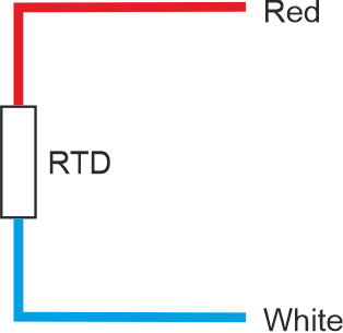
- As per the IEC-60751 standard, the lead wire colors typically used for 2-wire RTDs are Red and White.
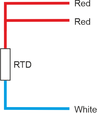
3 Wire RTD Configuration
- The 3-wire RTD configuration is widely used and highly suitable for temperature measurement in industrial processes and monitoring applications.
- In the 3-wire configuration, two wires are connected to one side of the sensor element and one wire is connected to the other side, creating a balanced bridge circuit.
- It is crucial to ensure that all three lead wires are made of the same material to maintain accurate temperature readings.
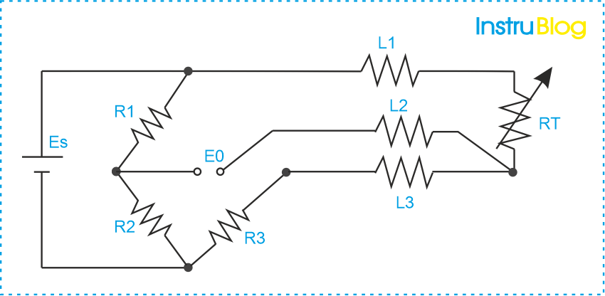
- The 3-wire RTD configuration consists of three lead wires: L1, L2, and L3, along with the RTD sensor.
- In the Wheatstone bridge setup, the supply voltage (Es) and output voltage (Eo) are connected to the RTD, while the three other leg resistors (R1, R2, and R3) complete the bridge circuit.
- The 3-wire RTD works by measuring the resistance difference between (L1 resistance + L2 resistance + RT) and (L2 resistance + L3 resistance), where RT represents the resistance of the RTD.
- All three lead wires, L1, L2, and L3, have the same resistance.
- The accuracy of temperature measurement using the 3-wire RTD configuration is significantly improved as it helps eliminate the impact of lead wire resistance to a great extent.
- Due to its enhanced accuracy, the 3-wire RTD configuration is highly suitable for various temperature measurement applications.
- As per the standard IEC-60751, the lead wire colors for the 3-wire RTD are Red, Red, and White.
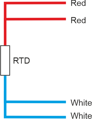
4 Wire RTD Configuration
- Among all RTD configurations, the 4-wire RTD stands out as the most accurate option.
- Unlike the 2-wire and 3-wire configurations, the 4-wire RTD not only eliminates the resistance introduced by the lead wires but also effectively eliminates additional resistances arising from contact points.
- By providing separate paths for the excitation current (carried by two wires) and voltage measurement (across the RTD via the remaining two wires), the 4-wire configuration ensures precise and reliable temperature measurements by minimizing potential errors.
- The 4-wire RTD is particularly well-suited for applications where high measurement accuracy is essential and where the elimination of lead wire and contact resistances is critical.
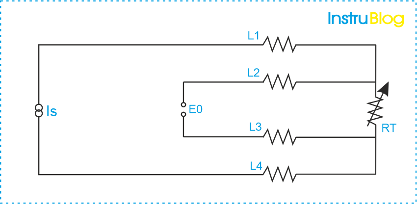
- The 4-wire RTD configuration utilizes four lead wires, namely L1, L2, L3, and L4. It operates by applying a known supply current (Is) and measuring the resulting output voltage (Eo).
- The resistance contributions from L1 and L4 combine to form the circuit with L2 resistance, L3 resistance, the actual RTD resistance (RT), and the voltage across the RTD (E0). Simple application of Ohm’s law allows us to determine the true resistance of the RTD.
- The voltage E0, obtained by multiplying the supply current (Is) by the RTD resistance (RT), represents the accurate RTD resistance value. Therefore, the 4-wire RTD configuration effectively eliminates the issues associated with lead wire resistance.
- 4-wire RTDs are highly suitable for temperature measurement applications in laboratories where stringent accuracy requirements are necessary.
- As per the standard IEC-60751, the recommended lead wire colors for 4-wire RTDs are Red, Red, and White. Adhering to this standard ensures proper identification and connection of the lead wires.
I hope you like above blog. There is no cost associated in sharing the article in your social media. Thanks for reading!! Happy Learning!!
0 Comment