
Table of Contents
ToggleDP Transmitter Level Measurement
In this blog, we are going to study how DP transmitter level measurement is used for open tanks and closed tanks.
Differential pressure transmitter has 2 tapings.
HP (High Pressure) Taping
LP (Low Pressure) Taping
With the help of the above two tapings, we level measurement can be done.
Lets understand first, why we are using DP Transmitters for level measurements.
There are many physical level measuring instruments available in the market. DP Flow Transmitter is utilized due to the need for monitoring the level signal from a remote-control room, eliminating the need for physical visits to the tank for level observation.
DP Transmitter Level Measurement for Open Tanks
DP Transmitter level measurements is used widely in various applications. Differential pressure transmitters are used for liquid level measurement, especially in open tanks.
When measuring level in a closed or pressurized tank, a DP measurement is necessary to compensate for vessel pressure.
In an open tank level measurement, the DP transmitter’s HP leg is connected to the bottom of the tank while the LP leg is open to the atmosphere.
Specific gravity, which is the density relative to the density of water, plays a crucial role in the configuration of the DP transmitter.
By determining the zero level and span level, the Lower Range Value (LRV) and Upper Range Value (URV) can be configured using a HART communicator.
Case 1 : DP Transmitter installed at the exact HP tapping point
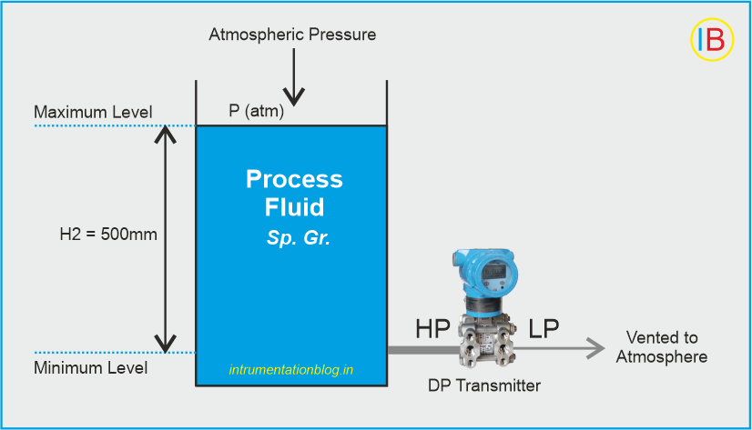
Lets see DP Transmitter level measurements in case where DP Transmitter is installed at the exact HP (High Pressure) tapping point.
At Zero level = 0 mmwc
At Span level = H x Specific gravity
= 500 x 1.0
= 500 mmwc
Case 2 : DP Transmitter Installed Below Tapping Point for Open Tank
Lets see DP Transmitter level measurements in case where DP Transmitter is installed below tapping point for open tank.
If the transmitter is installed below the tank then it is called zero suppression.
The calculations will be as below:
When zero suppression is used then H1 height always filled with process fluid.
At zero level (LRV) = H1 x specific gravity
= 100 x 1.0
= 100 mmwc
At 100% level (URV) = (H1 + H2) x specific gravity
= (100 + 500) x 1.0
= 600 mmwc
Range = URV – LRV = 600 – 100 = 500 mmwc
To accurately configure the DP transmitter for level measurement in an open tank, we have to set the Lower Range Value (LRV) to 100 mmwc (millimeters of water column) and the Upper Range Value (URV) to 600 mmwc using a HART communicator
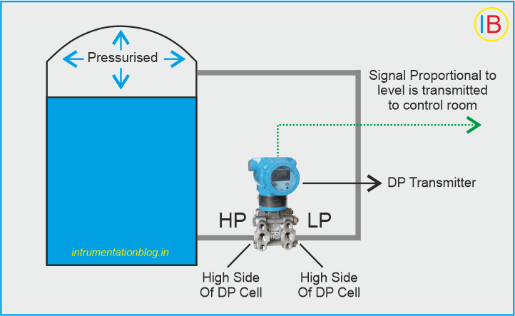
DP Transmitter Level Measurement for Closed Tanks
Lets see how DP Transmitter level measurements is used for closed tank applications.
Hydrostatic head instruments are utilized to measure liquid level in vessels operating above atmospheric pressure.
These instruments fully leverage the capabilities of differential pressure devices by connecting both sides of the measuring element to the vessel.
A differential pressure transmitter automatically subtracts the pressure on the LP (low pressure) side from the total pressure on the HP (high pressure) side. This configuration ensures that each increment of pressure above the liquid surface is counteracted by opposing capsule assemblies within the transmitter, resulting in cancellation.
Consequently, only the hydrostatic pressure exerted on the HP side contributes to the transmitter’s response, which is directly proportional to the level being measured.
The DP transmitter incorporates various pressure sensors such as diaphragms, capsules, and strain gauges to accurately measure the differential pressure. Depending on the specific pressure sensor used, the measured pressure is converted into parameters like millivolts, capacitance, or resistance.
To facilitate this conversion, a Wheatstone bridge is commonly employed, transforming the outputs of resistance, capacitance, or inductance-based pressure sensors into electrical signals such as millivolts or volts, proportionate to the pressure. Subsequently, the transmitter converts the pressure into an equivalent level signal.
In terms of installation, the tank’s bottom tapping point serves as the High Pressure (HP) tapping point, while the tank’s top tapping point functions as the Low Pressure (LP) tapping point.
The DP transmitter is connected to these HP and LP tapping points accordingly.
Please note that the calibration parameters of the DP transmitter may vary based on the specific installation and seal system employed.
Typically, three possible installation scenarios can be observed in the field.
| Installation Method | Advantages | Disadvantages |
|---|---|---|
| Transmitter installed Exactly at HP tapping point (Ideal & preferred way of installation) | Minimizes measurement errors and inaccuracies | Ensures accurate and reliable readings |
| Transmitter installed above HP tapping point | Reduces the chance of bubble formation in impulse line | May introduce errors due to potential bubble formation |
| Transmitter installed below HP tapping point | Effective compensation for measurement errors | May require additional calibration and adjustment |
The calibration process for the transmitter is determined by the specific installation method in the field. The calibration formula may vary slightly based on the installation type.
Two crucial parameters for every transmitter are the Lower Range Value (LRV) and Upper Range Value (URV). These values need to be calculated based on the installation method.
Wet Leg and Dry Leg Methods
Wet Leg: In this configuration, the LP impulse line is filled with liquid such as water, glycol, glycerin, or the same liquid present inside the tank.
Dry Leg: In this configuration, the LP impulse line is filled with air, gas, or any other gases.
The hydrostatic pressures applied to DP transmitters will vary depending on whether it is a wet leg or dry leg installation. It is important to consider these factors as the calibration formula will also vary accordingly.
The decision of whether a DP transmitter has a wet leg or dry leg configuration can be made based on its field installation and process application. In some cases, a dry leg installation can be converted to a wet leg by filling water into the LP impulse line.
Case 1 : Transmitter mounted leveled with the minimum level
With wet leg, Span = ρp • g • H , or, = SGp • h
With dry leg ; Span = ρp • g • H , or, = SGp • h
Case 2 : Transmitter mounted above the minimum level
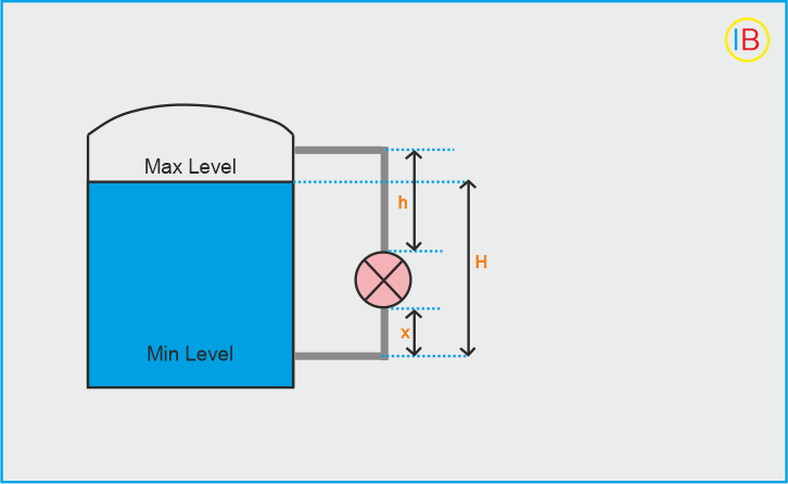
With wet leg, Zero Elevation = − (ρf • g • x)
Span = ρp • g • H
With dry leg, It is not preferable
So, for calibration,
4mA (LRV) = Min. Head + Zero Elevation
20mA (URV) = Span + Zero Elevation
Case 3 : Transmitter mounted below the HP tap
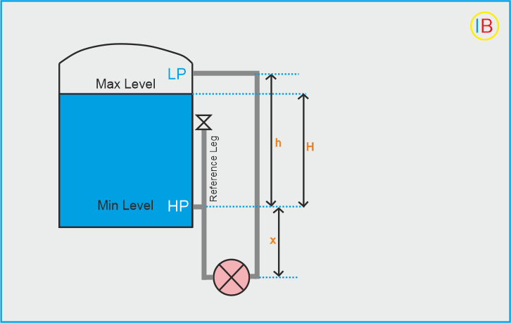
With dry leg,
Pw at min. level = (SGf • x)
Pw at max. level = (SGf • x) + (SGp • H)
Span = SGp • H
With wet leg,
Zero Suppression = − (ρf • g • h) ,or, = − (SGf • h)
Span = ρp • g • H , or, = SGp • H
Therefore, for calibration;
4mA (0%) = Zero Elevation
20mA (100%) = Span+Zero Suppression
Case 4 : Transmitter mounted below HP tapping point and Minimum Level is Elevated
Wet Leg:
Minimum Wet Leg Pressure (Pw min): Calculated as (SGp • y) – (SGf • d)
Maximum Wet Leg Pressure (Pw max): Calculated as (SGp)(x + y) – (SGf • d)
Span: Calculated as ρp • g • x or SGp • x
Dry Leg:
Pressure at Minimum Level (Pw at min. level): Calculated as (SGf • z) + (SGp • y)
Pressure at Maximum Level (Pw at max. level): Calculated as (SGf • z) + (SGp)(x+y)
Span: Calculated as SGp • H
Please have a look with below variables and their definitions:
| Variable | Definition |
|---|---|
| ρp | Density of process liquid in the tank |
| ρf | Density of fill-liquid in the tubing |
| ρu | Density of upper liquid |
| ρl | Density of lower liquid |
| Pw | Equivalent head of water |
| SGp | Standard gravity of process liquid |
| SGf | Standard gravity of fill liquid |
| SGu | Standard gravity of upper liquid |
| SGl | Standard gravity of lower liquid |


I hope you like above blog. There is no cost associated in sharing the article in your social media. Thanks for Reading !! Happy Learning
3 Comments