
555 Timer IC Explained: Astable, Monostable, and Bistable Modes
Designed in 1971 with nothing but 25 transistors, 2 diodes, and 15 resistors, the 555 has outlived entire generations of newer chips because three resistors and a capacitor are still the fastest way to get a precise pulse or oscillation.
The 555 timer is one of the most widely produced integrated circuits ever made, generating precise time delays and oscillations from just a handful of external resistors and capacitors. This guide covers its internal block diagram, all three operating modes, the timing formulas, and a live astable calculator.
What is a 555 Timer IC?
The 555 Timer is an 8-pin integrated circuit, originally designed by Hans Camenzind in 1971, that produces accurate time delays or oscillations using an external resistor-capacitor (RC) network. Despite its age, it remains one of the best-selling ICs in history, found in everything from toys and kitchen appliances to industrial timer circuits and even spacecraft.
Internally, a standard 555 contains 25 transistors, 2 diodes, and roughly 15 resistors, arranged into two voltage comparators, a flip-flop, a discharge transistor, and an output stage. Three internal 5 kΩ resistors form a voltage divider that sets reference voltages at exactly 1/3 and 2/3 of the supply voltage, which is actually where the chip's name comes from.
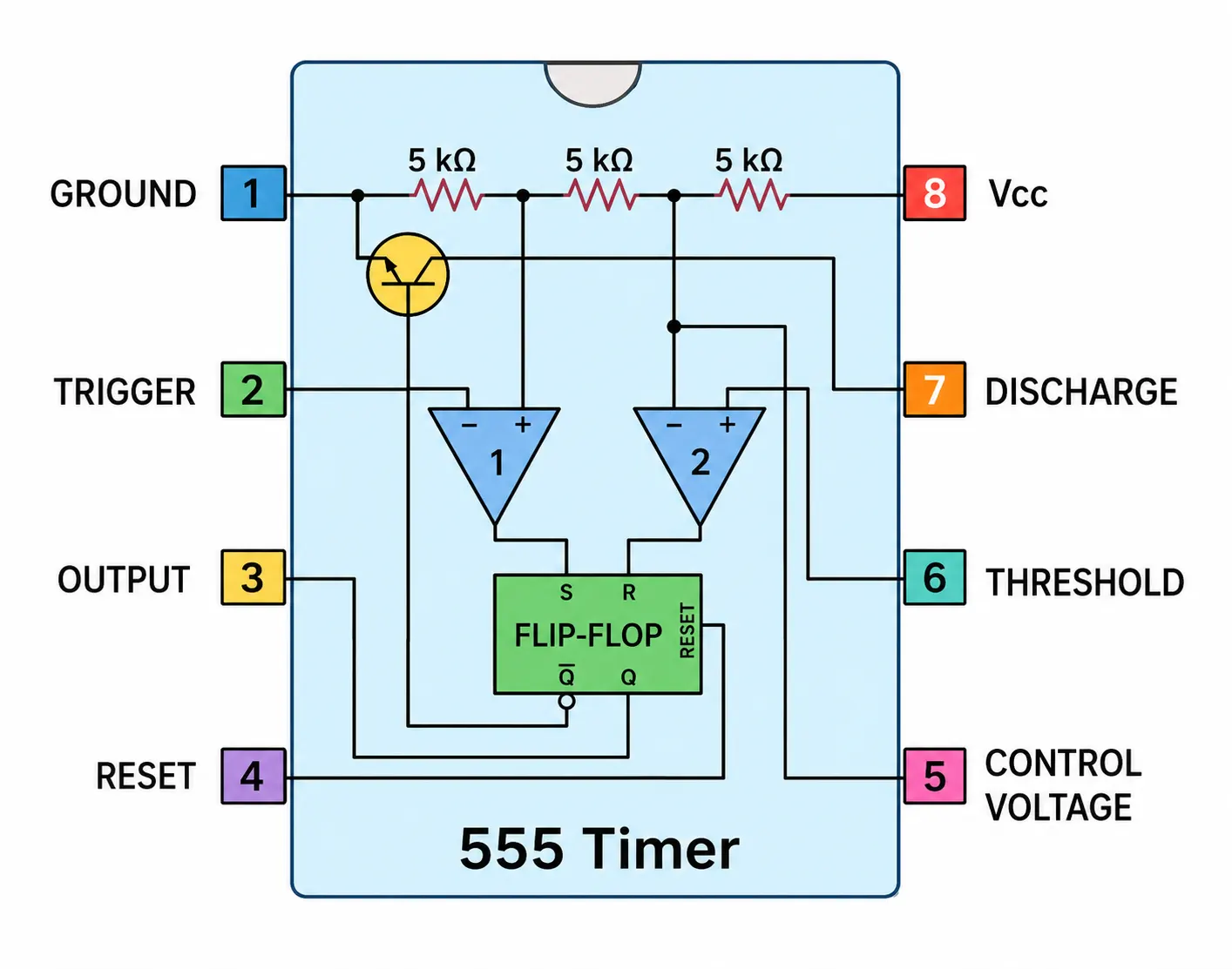
555 Timer Block Diagram?
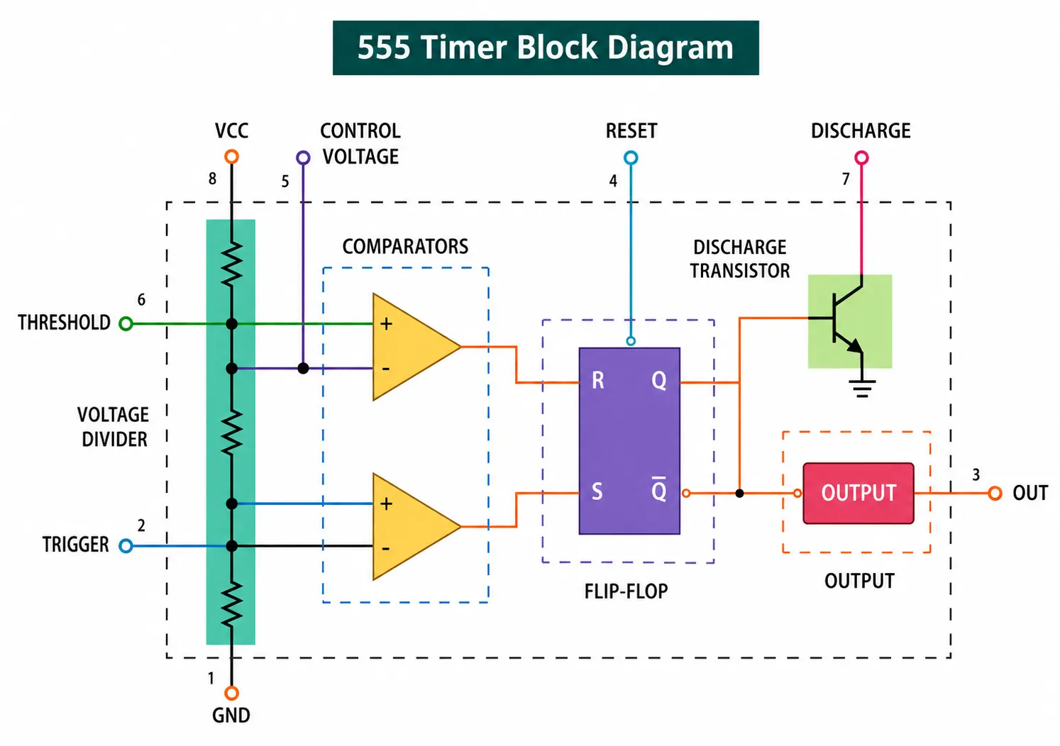
Real Life Example
Think of the 555 astable mode as a light switch nobody is holding, one that keeps flipping itself on and off forever at a steady rate, like a blinking turn signal. The monostable mode is more like a bathroom exhaust fan with a timer switch: press it once, and it stays on for a fixed duration before turning itself back off, no matter how long you press the button.
The Three Operating Modes
🔄 Astable Mode
⏱️ Monostable Mode
🔀 Bistable Mode
555 Timer Formulas
555 Timer Astable Calculator
Astable Frequency and Duty Cycle Calculator
Classic two-resistor, one-capacitor astable configurationComparing the Three Modes
Applications of the 555 Timer
LED and Lamp Flashers
Astable mode drives blinking indicators and warning lights at a set rate.
Tone Generators
Astable oscillation drives simple alarm and buzzer tone circuits.
Delay Timers
Monostable mode provides fixed delay-on or delay-off timing for control circuits.
Switch Debouncing
Monostable pulses clean up noisy mechanical switch contacts before feeding logic circuits.
Servo Motor Testing
Monostable pulse widths in the 1 to 2 ms range mimic standard servo control signals.
Frequency Division
Combined with counters, 555 astable output supports clock division circuits.
555 Timer IC: Video Walkthrough
Frequently Asked Questions About the 555 Timer
- Electronics Tutorials, 555 Timer Tutorial, The Monostable Multivibrator
- Electronics Tutorials, 555 Oscillator Tutorial, The Astable Multivibrator
- How To Mechatronics, 555 Timer IC Working Principle
What We Learn Today
- The 555 timer is a robust 8-pin IC that generates precise time delays or oscillations from a simple external RC network
- Astable mode oscillates continuously with no stable state, monostable produces one timed pulse per trigger, bistable acts as a simple flip-flop
- Monostable pulse width follows T = 1.1RC, while astable frequency follows f = 1.44/((R1+2R2)C)
- A classic two-resistor astable circuit can never reach exactly 50% duty cycle without circuit modification
- Despite decades of newer alternatives, the 555 remains a go-to choice for simple, low-cost timing applications