
Every field transmitter, switch and valve signal passes through a junction box before it reaches the control room. A well designed box keeps those signals safe, dry, segregated and easy to trace for the whole life of the plant.
A junction box looks like a simple steel enclosure, yet poor design causes water ingress, noise, wrong wiring and hazardous area failures. This guide covers the practical rules for designing and specifying one correctly.
What Is an Instrument Junction Box?
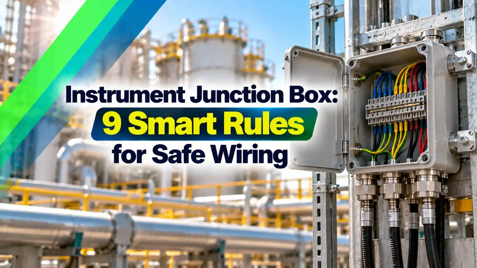
An instrument junction box is a field enclosure where the individual cables from several instruments are terminated and joined to one multicore cable that runs to the control room. It reduces the number of long cables, keeps terminations protected and gives a convenient point for testing and fault finding.
In a typical plant, the field JB sits between the instruments and the marshalling cabinet. From there the signals go to the DCS, PLC or safety system input cards.

The same box idea is used for analog loops, digital signals, thermocouples, fieldbus spurs and power to solenoids. How the cables are routed from the field to the system is shown in PLC wiring from field instrument to system cabinet.
Single Pair and Multi Pair Instrument Junction Box Types
Terminates one instrument cable, often for a splice or a remote device.
Collects 6 to 48 or more field pairs onto one or two multicore cables.
Holds device couplers, spur protection or solenoid power terminals.
Each multicore pair carries one loop, such as a 4 to 20 mA current loop, with an overall shield and often an individual shield per pair. Thermocouple extension cables need their own JB with compensating terminals.
Many specifications ask for multicore cables with two or more unused pairs left for future use. Control and Instrumentation recommends this so new instruments can be added without pulling a new cable.
9 Design Rules for an Instrument Junction Box
Mount the box so that all glands enter from the bottom. Top entry glands collect rainwater and are the most common cause of water inside a JB.
Terminal Sizing and Spare Philosophy
When sizing an instrument junction box, count the terminals for every core, then add separate terminals for each pair shield and the overall shield. A 3 wire RTD or a 4 wire loop needs more terminals than a 2 wire transmitter, so read the instrument list carefully.
Most projects keep about 10 to 20 percent spare terminals and spare multicore pairs, as specified by the client. Spare cores should be terminated on spare terminals and labelled, not left loose inside the box.
Spare terminals = Used terminals × Spare % ÷ 100
Multicore pairs ≥ Instruments × (1 + Spare % ÷ 100)
Example:
20 transmitters, 3 terminals each (plus, minus, shield), 20 percent spare
Used = 20 × 3 = 60, spare = 60 × 20 ÷ 100 = 12
Total terminals = 72, multicore pairs at least 24
Choose terminals rated for the conductor size, usually 1.5 or 2.5 square mm for signals. Disconnect or knife terminals on loops help testing without lifting wires, and fused terminals suit solenoid power.
Junction Box Terminal Calculator
Second Worked Example: Mixed Signal Area
A compressor skid has 14 transmitters with 3 terminals each and 6 RTDs with 4 terminals each, and the client wants 15 percent spare. Used terminals are 14 × 3 plus 6 × 4, which is 66, and the spare is 66 × 0.15, rounded up to 10.
The box therefore needs at least 76 signal terminals, plus end stops, earth bar and markers. The multicore needs at least 20 × 1.15, rounded up to 23 pairs, so the next standard 24 pair cable is chosen.
IS and Non IS Segregation Inside the JB
Intrinsically safe circuits must stay separate from non IS wiring, as explained in explosion proof vs intrinsically safe instruments. The simplest and preferred way is a dedicated IS instrument junction box with only IS circuits inside.
IEC 60079 14 requires a clearance of at least 50 mm between IS and non IS terminals when they share a box, or an earthed metal or insulating partition. IS terminals and cables are normally coloured light blue so they are easy to identify.
Control and Instrumentation notes that boxes holding IS circuits are labelled on the outside, blue with white lettering, stating Intrinsically Safe Circuits. This warns electricians not to connect any other circuit or test equipment that is not IS approved.
An Ex e increased safety box can hold IS circuits as well, but the IS terminals still need the same segregation and blue identification. The Ex e rating does not make the IS circuit any safer by itself.
Ex e, Ex d and Hazardous Area Choices
In a classified area, the instrument junction box must suit the zone from the hazardous area classification, the gas group and the temperature class. The ABS guidance note asks for Gas Group II and temperature class T3 as a minimum for offshore junction boxes.
| Protection | How It Protects | Gland Entry | Typical Use |
|---|---|---|---|
| Ex e increased safety | No sparks, controlled terminals and creepage | Bolted gland plate, Ex e glands | Most instrument JBs in Zone 1 and 2 |
| Ex d flameproof | Contains an internal explosion | Threaded entries, Ex d glands and plugs | Boxes with sparking parts or power |
| Ex i intrinsic safety | Limits energy in the circuit | Normal IP rated glands | IS loops, blue labelled |
| Non Ex industrial | No hazardous area protection | Industrial glands | Safe areas only |
Ex e boxes are lighter and easier to wire, so they are the usual choice for instrument signals. For certification, the box needs ATEX or IECEx marking, compared in difference between ATEX and IECEx.
IP Rating, Material and Cable Glands
Control and Instrumentation states that IP56 is usually the minimum for junction boxes, especially outdoors. The ABS note lists IP21 for indoor rooms with HVAC, IP44 for machinery spaces, IP54 with water mist and IP56 outdoors, as described in IP rating explained.
SS316L is the preferred material in coastal and offshore plants because it resists chloride corrosion, while GRP suits chemical areas and is light. ABS recommends SS316L gland plates with nickel plated brass glands for offshore boxes.
Glands must carry the same Ex certification and IP rating as the instrument junction box, and unused entries need certified stopping plugs. Armoured cables need glands that clamp and earth the armour, as covered in cable gland types and selection.
Fit a breather drain at the lowest point of a large outdoor box. It lets condensation escape without letting rain in, which keeps terminals dry during the monsoon.
Earthing and Shield Termination
The instrument junction box body needs an external earth stud, and the ABS note recommends M6 to M10 SS316L studs welded to the enclosure so the IP rating is not lost. The protective earth follows the plant earthing scheme.
Cable shields are landed on an isolated instrument earth bar, not on the box body, and are earthed at one end only, usually the control room. This avoids the circulating currents described in ground loop causes and prevention.
Labelling and the JB Schedule
Each instrument junction box carries a tag plate with its JB number, area and protection marking, and every terminal and core gets a ferrule matching the drawings. Good labels make loop checks and later maintenance far faster.
The JB schedule lists every instrument tag, field cable, terminal number, multicore cable and pair number for each box. It is the key document used during the instrument loop checking procedure at commissioning.
Use the plant colour code for cores and shields, following the practice in cable colour codes for field instruments. Keep the schedule updated after every modification so the as built records stay true.
- Box tag, area classification and Ex marking verified
- IP rating and material match the specification
- All glands certified, tight and unused entries plugged
- IS and non IS circuits segregated and blue labelled
- Terminals, ferrules and cores match the JB schedule
- Spare terminals and pairs terminated and labelled
- Shields on isolated bar, earth stud connected
- Insulation resistance and continuity tests recorded
Instrument Junction Box Installation and Testing
Mount the instrument junction box on a rigid stand at a convenient working height, away from heat sources and vibration, with clear access for the door. Route cables neatly on trays sized with the cable tray fill calculation.
Before energising, carry out continuity and insulation resistance tests on every pair. Follow this with the loop check from the field device to the control system screen.
- Fewer long cables and lower installation cost.
- Easy testing and fault finding at one point.
- Safe segregation of IS and non IS circuits.
- Room for future instruments through spares.
- Extra connection points that can loosen.
- Water ingress if glands or gaskets fail.
- Needs certified parts in hazardous areas.
- Poor labelling makes troubleshooting slow.
Where Field JBs Are Used
For safety related loops, many owners keep separate boxes for the fire and gas system and the shutdown system. Noise sensitive loops also benefit from shielded twisted pair cable through the box.
ABS Guidance Note on Junction Boxes
Junction Box Installation Rules Video
Instrument Junction Box FAQ
It is a field enclosure where cables from several instruments are terminated and joined to a multicore cable. The multicore then carries all those signals to the control room.
It reduces cable cost and gives a safe point for testing and fault finding. Each box is tagged and recorded in the JB schedule for traceability.
Most projects keep about 10 to 20 percent spare terminals, as specified by the client standard. Spare multicore pairs are also left so future instruments can be added without a new cable.
Spare cores should be terminated on spare terminals and labelled clearly at both ends. Loose spare cores inside the box can touch live terminals and cause faults.
It is possible only with at least 50 mm clearance or an approved partition between the terminals. Even then, the IS terminals and wiring must be clearly identified in light blue.
Most designers prefer a dedicated IS box to avoid any mistakes during later work. That box is labelled on the outside as containing intrinsically safe circuits.
An Ex e box prevents sparks and hot spots through controlled terminals, creepage distances and good sealing. It is light and easy to wire, so it suits most instrument signals.
An Ex d box is strong enough to contain an internal explosion without passing flame outside. It is heavier and needs threaded entries with certified Ex d glands and plugs.
Control and Instrumentation considers IP56 the usual minimum for outdoor junction boxes in process plants. The ABS offshore guidance also lists IP56 for outdoor locations on offshore units.
Areas with frequent washdown or heavy monsoon rain may need IP66 or better protection. Glands, plugs and breathers must hold the same rating, or the overall box rating is lost.
Signal shields are normally earthed at one end only, usually at the control room instrument earth bar. In the field box they are carried through on an isolated shield terminal or bar.
Earthing at both ends can create a ground loop that injects noise into the signal. Always follow the earthing philosophy written in the project specification.
It is a document listing every instrument, field cable, terminal and multicore pair for each junction box. Engineers use it to wire, check and later maintain every connection.
The schedule is a key reference during loop checks and plant modifications. Keep it updated after every change so it always matches the real wiring inside each box.
Related Articles
- Marshalling Cabinet DCS Wiring
- Cable Gland Types and Selection
- Explosion Proof vs Intrinsically Safe Instruments
- Hazardous Area Classification Zones
- IP Rating Explained
External References
- Junction Box and Cable Tray Guidance Notes, American Bureau of Shipping
- Instrument Junction Boxes Selection and Specification, Control and Instrumentation
- Junction Box, Wikipedia
What We Learn Today
- An instrument junction box joins many field cables to one multicore, cutting cable cost and giving a protected point for testing, wiring changes and fault finding.
- Good design groups signals by type, segregates IS circuits, keeps 10 to 20 percent spares and matches Ex protection, IP rating and glands to the area.
- Terminal count equals instruments times terminals per loop plus spares, so 20 three terminal loops with 20 percent spare need 72 terminals.