
Level Measurement · Interface · Oil and Water Separation · Process Instrumentation
Interface Level Measurement: 7 Technologies Explained with Applications and Selection Guide
In oil and gas, chemical, and petrochemical plants, tanks frequently hold two liquids that separate into layers due to density differences. Knowing exactly where these layers meet (the interface) is critical for product quality, equipment protection and operating efficiency. This guide explains seven technologies used for interface level measurement, their working principles, advantages, limitations and how to choose the right one.
What Is an Interface in a Process Tank?
An interface is the boundary layer between two immiscible liquids (liquids that do not mix) inside a tank or vessel. Because the two liquids have different densities, the heavier one settles at the bottom and the lighter one floats above it. The point where they meet is the interface.
Common examples in industrial plants include:
- Crude oil over produced water in oil-gas separator vessels
- Diesel over green diesel in refinery blending tanks
- Soap over black liquor in pulp and paper mill white liquor tanks
- Methanol over water in chemical separation columns
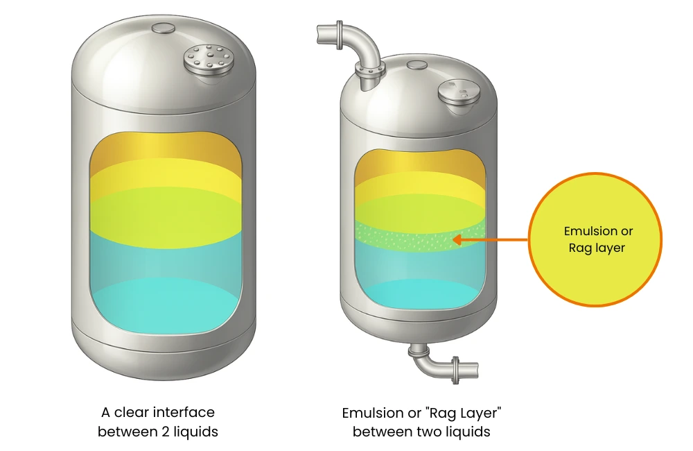
The situation is not always a clean two-layer separation. Between the two liquids there is often a rag layer (also called an emulsion layer), a cloudy transition zone where the two fluids partially mix. This makes interface detection more difficult and is a key factor in choosing the right measurement technology.
Why Interface Level Measurement Matters in Process Plants
Accurate interface level measurement directly affects plant profitability, product quality and equipment reliability. Specifically, operators need interface data to:
- Prevent water carryover into oil-processing systems, which causes corrosion, catalyst poisoning and downstream equipment damage
- Avoid oil losses with water drawoff, where valuable hydrocarbon is sent to waste along with the water phase
- Maintain correct residence time in separators so that adequate separation occurs before each phase exits
- Control chemical dosing for demulsifiers that break the rag layer
- Meet environmental discharge limits on oil content in produced water
Even a small error in interface detection (say 50 mm) can translate into thousands of litres per day of oil contaminating the water outlet, or water contaminating the oil outlet. In high-throughput oil separators, this is a significant financial and environmental consequence. Reliable level measurement at the interface is therefore as important as measuring the total liquid level in the vessel.
7 Technologies Used for Interface Level Measurement
A float is a buoyant device that rides on the surface of the upper liquid. In a two-layer system, it measures the total liquid surface level (the top of the upper layer), not the interface itself. A displacer is different: it is a heavy, fully submerged rod or cylinder that does not float. Instead, it uses Archimedes' principle: the buoyant force on the displacer changes as it crosses from one liquid into another. When configured for the known densities of both liquids, the displacer transmitter can calculate the interface position from the changing buoyant force it experiences.
The key requirement is that the densities of both liquids must be known and stable. For a DP transmitter or displacer, the calculation relies on stable specific gravity values. If the oil density changes with temperature or composition, the displacer reading becomes unreliable without density compensation.
- Simple and low cost
- No power needed for basic float types
- Well-understood by field technicians
- Suitable for low-pressure non-hazardous tanks
- Requires known, stable liquid densities
- Turbulence causes instability
- Rag layer confuses the displacer reading
- Moving parts need maintenance
Typical applications: Simple oil-water separator vessels, storage tanks, industrial water treatment.
A capacitance probe is a rod or cable inserted vertically into the tank. It acts as one plate of a capacitor; the tank wall or a reference electrode is the other plate. The dielectric constant (permittivity) of the liquid between them determines the capacitance. Since oil is non-conductive (low dielectric constant around 2) and water is highly conductive (high dielectric constant around 80), the capacitance changes sharply at the oil-water interface. The electronics measure this change continuously and convert it to an interface position signal.
Capacitance sensors are commonly wired with 4-20 mA outputs to DCS or PLC systems. Some smart versions also communicate via HART for remote configuration and diagnostics.
- Good sensitivity at the interface zone
- Works with rag layers present
- Compact for small or narrow tanks
- Continuous measurement, not point-level
- Accuracy drops if fluid conductivity varies
- Probe coating by viscous fluids causes error
- Not ideal when product types change frequently
- Measures interface OR conductive layer thickness, not both simultaneously
Typical applications: Chemical mixing tanks, oil-water separators, food and beverage, pharmaceutical processing.
Guided Wave Radar is one of the most widely used technologies for interface measurement in modern process plants. A microwave signal (typically 1-2 GHz) travels down a probe (rod or cable) immersed in the liquid. When the radar signal encounters a change in dielectric constant, such as at the oil-gas surface or the oil-water interface: part of the signal reflects back to the instrument. By measuring the time-of-flight of each reflection, the GWR transmitter calculates both the total level (surface of upper liquid) and the interface level simultaneously from a single probe.
GWR works because oil and water have very different dielectric constants (oil dk 2, water dk 80). The signal strongly reflects at the oil-water interface because of this contrast. The minimum required difference in dielectric constant between the two liquids is typically dk 10, which the oil-water pair far exceeds. Related to how radar signals behave in process vessels, the same principles govern DP transmitter level measurement where hydrostatic head rather than electromagnetic waves is used.
- Measures both total level AND interface simultaneously
- Not affected by density, pressure or vapour
- Works in pressurised and high-temperature vessels
- No moving parts, low maintenance
- HART or FOUNDATION Fieldbus communication
- Requires dk difference of at least 10 between liquids
- Thick rag layers can attenuate the interface echo
- Probe must be properly configured for multi-layer detection
- Higher cost than floats or capacitance for basic applications
Typical applications: Oil-water separators, crude oil storage, refinery desalters, condensate drums, fuel storage vessels.
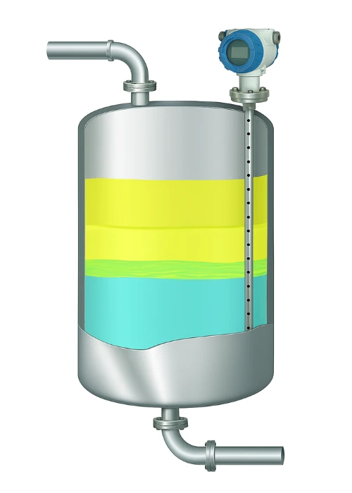
Multi-parameter sensors combine guided wave radar and capacitance measurement in a single probe. When the radar signal is blocked or attenuated by a thick emulsion or rag layer (which has intermediate dielectric properties that weaken the interface echo), the device automatically switches to capacitance mode to detect the conductive water layer beneath. This hybrid approach handles the most challenging interface applications where neither technology alone is reliable.
- Handles thick and variable rag layers
- Gives total level + interface + rag layer thickness
- Automatically selects best measurement mode
- Highly reliable in unpredictable fluid conditions
- Higher cost than single-technology probes
- Requires skilled commissioning and configuration
- May be oversized for simple two-layer systems
Typical applications: Advanced oil-water-gas three-phase separators, tanks with variable emulsion layers, refining and high-precision chemical processing.
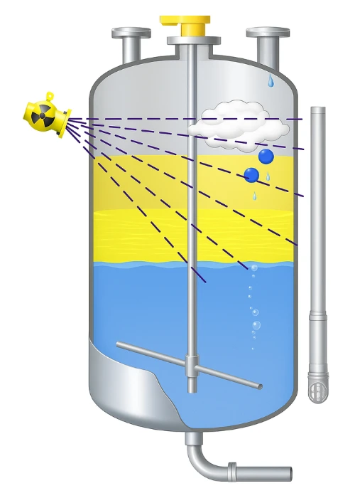
Gamma level gauges use a radioactive source (typically Caesium-137 or Cobalt-60) mounted on one side of the vessel and a scintillation detector on the opposite side. The gamma radiation passes through the vessel wall and the process liquid. Denser liquids (water, sludge) absorb more radiation, so less reaches the detector. Lighter liquids (oil, gas) absorb less. By measuring the radiation intensity at different heights using multiple detectors or a continuous detector array, the system can map the complete level profile inside the vessel without any process contact.
- Completely non-invasive: no process connections
- Works through any vessel wall including thick-walled pressure vessels
- Detects foam, vapour, sludge and multiple interfaces
- No process shutdown required for installation
- No moving parts, highly reliable
- Requires nuclear safety regulatory permits
- Highest cost of all interface technologies
- Needs specially trained personnel for installation and compliance
- Radiation source must be handled, transported and disposed of safely
Typical applications: Heavy crude oil separators, coke drums, high-pressure chemical reactors, multiphase separators where no process nozzles are available.
Ultrasonic sensors transmit sound pulses (typically 40 kHz to 200 kHz) into the liquid. When the pulse hits a layer of solid material such as settled sludge, salt cake or sediment, the acoustic impedance difference causes the pulse to reflect back. The time-of-flight gives the distance to the solid-liquid interface. Ultrasonic is particularly effective for sedimentation and thickener applications where a solid layer settles at the bottom of a liquid-filled tank.
Note that standard ultrasonic sensors are not suitable for liquid-liquid interface measurement (oil-water boundary) because the acoustic impedance difference between oil and water is too small to produce a reliable reflection. The reflection coefficient depends on density and sound speed differences, and oil-water pairs have insufficient contrast for most practical ultrasonic detectors at industrial frequencies.
- Excellent for solid-liquid interfaces (sludge, sediment)
- Can be mounted externally (clamp-on ultrasonic)
- No radiation hazards
- Works well in wastewater and mining applications
- Does NOT reliably detect liquid-liquid interfaces (oil/water)
- Foam and bubbles scatter the acoustic signal
- Uneven sedimentation causes reading uncertainty
- Temperature affects sound speed and accuracy
Typical applications: Sludge monitoring in wastewater treatment, brine and salt separation tanks, mining thickeners, clarifiers.
A differential pressure (DP) transmitter connected with tapping points at the top and bottom of a two-liquid zone can estimate the interface level if both liquid densities are known and stable. The total hydrostatic head measured by the DP cell equals the sum of contributions from each liquid layer. If total level is known from a separate measurement, the interface position can be calculated mathematically. This approach is widely used in existing plants as a low-cost add-on because most vessels already have DP transmitters for other purposes.
Sight glasses provide direct visual confirmation of the interface position for local operators. Bubble tubes blow a small air or gas flow from the bottom of the tank, and the back-pressure provides a level indication. Both sight glass and bubble tube methods are best suited for non-hazardous, low-pressure backup readings or training applications, not for precise continuous control.
- Very low cost, uses existing equipment
- DP cells provide a 4-20 mA output compatible with all DCS/PLC systems
- Sight glass gives immediate visual confirmation
- Well-understood by all plant personnel
- Requires accurate, stable density data for both liquids
- Cannot show the rag layer or its thickness
- Sight glass: manual reading only, cannot be used for automatic control
- Bubble tubes can become clogged in viscous or scaling fluids
Typical applications: Small tanks, backup readings, educational demonstrations, cost-sensitive applications where precision is not critical.
Interface Level Measurement Technology Selection Guide
Choosing the right interface measurement technology depends on the nature of the liquids, the presence of rag layers, process conditions and budget. Use this table as a starting point. Always confirm with the process details specific to your application and consult with an experienced level measurement specialist for final selection.
| Technology | Liquid pair type | Rag layer? | Measures total level too? | Invasive? | Relative cost |
|---|---|---|---|---|---|
| Float / Displacer | Any two liquids with known stable densities | No (confuses reading) | Float only (total level) | Yes | Very Low |
| Capacitance probe | Conductive vs non-conductive pair (e.g. water/oil) | Partial | No (interface only) | Yes | Low to Medium |
| Guided Wave Radar | Liquids with dk difference greater than 10 | Thin layers only | Yes (both levels) | Yes | Medium |
| Multi-parameter (GWR + Cap) | Any liquid pair with conductive lower liquid | Yes (handles thick rag) | Yes (all three: gas-oil-water) | Yes | High |
| Gamma radiometric | Any liquid or solid-liquid pair | Yes (full profile) | Yes (full vertical profile) | No (external) | Very High |
| Ultrasonic | Solid-liquid only (sludge, sediment) | N/A | Depends on mount | No (clamp-on) | Low to Medium |
| DP cell / Sight glass | Any two liquids with known stable densities | No | With calculation only | Yes (DP taps) | Very Low |
- What are the two liquids and their specific gravity values? How stable are those values?
- Do the liquids form a rag layer? How thick is it and does it vary?
- Do you need just the interface, or interface plus total level?
- Is the tank pressurised, heated or in a hazardous area?
- Are process nozzles available, or do you need a non-invasive solution?
- What signal output does your DCS or 4-20 mA loop system require?
- What is the maintenance access situation and calibration frequency required?
Quick FAQs: Interface Level Measurement
- DP Transmitter Level Measurement: Working Principle and Calculation
- DP Level Transmitter Zero Suppression and Elevation: Formula and Calculator
- 4-20 mA Current Loop: How Level Transmitter Signals Are Wired to DCS
- What Is a pH Sensor and How Does It Work: Another Key Analytical Measurement
- Turndown Ratio in Flow Meters: Selection Principles That Also Apply to Level Instruments
External References
- Emerson: Guided Wave Radar for Interface Level Measurement
- VEGA: VEGAFLEX Guided Wave Radar Interface Applications
- Endress+Hauser: Level and Interface Measurement Technology Guide
What we learn today
- Interface level measurement detects the boundary between two immiscible liquids of different densities (e.g. oil and water) in a process tank. A rag or emulsion layer between the two phases makes detection harder and is the key challenge most technologies must handle.
- Guided Wave Radar (GWR) is the most widely used modern technology: it measures both total level and interface simultaneously from one probe, requires no stable density data, and handles most oil-water applications. Multi-parameter sensors add capacitance to handle thick rag layers. Gamma gauges are used where no process nozzles are available.
- The right technology depends on: the specific gravity difference between the two liquids, whether a rag layer is present, whether total level plus interface is needed, process pressure and temperature, and whether an invasive or non-invasive installation is required.


2 Comments