
Thermal Overload Relay Working Principle: Bimetallic Strips, Trip Class, and Sizing
Two strips of metal, glued together, bending at different rates when heated, is the entire mechanism standing between a slightly overloaded motor and a burned-out winding.
A thermal overload relay protects a motor from sustained overload current using nothing more complex than a heated, bending bimetallic strip. This guide explains the working principle, trip classes, ambient compensation, and how to correctly size one for a motor starter.
What is a Thermal Overload Relay?
A thermal overload relay (OLR) is a protective device that trips a motor starter's contactor when current stays above a set value for long enough to risk overheating the motor. It protects specifically against sustained overload, not short circuits, which remain the job of a fuse, MCB, or MCCB installed upstream in the same circuit.
The most common design uses a bimetallic strip, two metals with different thermal expansion rates bonded together. As overload current heats the strip, unequal expansion causes it to bend. Once it bends far enough, it trips a mechanism that opens a normally closed contact wired in series with the contactor coil, dropping the contactor out and stopping the motor.
Real Life Example
Think of the bimetal strip like the coiled thermostat spring in an old-fashioned oven or iron. Mild warmth barely moves it at all, but sustained heat, held long enough, eventually bends it enough to trigger a switch. A thermal overload relay uses that same physical trick, just powered by the motor's own current instead of ambient heat, tuned specifically to mimic how a motor winding actually heats up under a sustained overload.
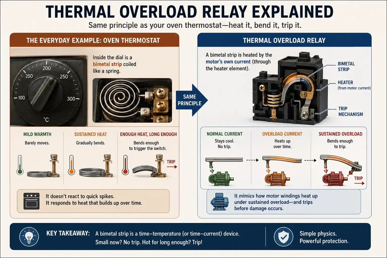
How a Bimetallic Thermal Overload Relay Works
Current Flows Through Heater
Motor current passes through a heating element wired in series with the motor circuit.
Bimetal Strip Heats Up
Heat from the element warms a bimetallic strip made of two bonded metals with different expansion rates.
Strip Bends and Trips
Once heated enough, unequal expansion bends the strip far enough to trigger the trip mechanism.
Contactor Drops Out
The trip opens a normally closed contact in the contactor coil circuit, stopping the motor.
Heating can be direct, where the full motor current flows through the bimetal strip itself, or indirect, where the strip sits near an insulated heating element carrying the current. Larger motors, typically above about 100A, use current transformers to step down the sensed current before it reaches the relay, reducing heat losses and easing the relay's own current rating requirements.
Trip Class Explained
Trip class defines how long a relay tolerates a sustained overload before tripping, standardized under IEC 60947-4-1. It is expressed as the maximum trip time at 7.2 times the relay's set current.
Choosing too fast a trip class for a motor with a genuinely long starting time causes nuisance tripping during every normal start. Choosing too slow a trip class for a fast, light motor delays protection unnecessarily during a real fault.
Sizing a Thermal Overload Relay
The relay's current setting is typically adjusted to between 100% and 115% of the motor's rated full load current (FLA) from the nameplate, accounting for service factor and ambient temperature. Where the relay sits in a Star-Delta circuit changes this calculation significantly: a relay wired to sense line current is set to the full FLA, while one wired inside the delta loop, sensing phase current, must be set to FLA divided by the square root of three, since phase current runs lower than line current by that same factor.
Applications
Industrial Motor Starters
Standard protection paired with contactors in DOL, Star-Delta, and soft starter circuits.
Pump Motors
Protects against sustained overload from clogged lines, cavitation, or mechanical binding.
HVAC and Fan Motors
Guards against overheating from blocked airflow or bearing failure.
Conveyor and Material Handling
Protects motors from jams and mechanical overload conditions.
Compressor Motors
Combined with trip class selection matched to compressor starting characteristics.
General Machine Tools
Basic, reliable overload protection with no external power supply required.
Common Selection Mistakes
✅ Do This
- Set the relay current based on the motor's actual FLA and service factor, not a guess
- Correct for phase versus line current when setting a relay inside a Star-Delta loop
- Match trip class to the motor's actual starting time and load inertia
- Use ambient-compensated relays in enclosures with significant temperature swings
❌ Avoid This
- Assuming a thermal overload relay provides short-circuit protection
- Setting a delta-loop relay to full line current instead of FLA divided by √3
- Choosing a trip class too fast for a genuinely long-starting, high-inertia load
- Ignoring repeated cycling on automatic reset relays, which can still damage the motor over time
Thermal Overload Relay: Video Walkthrough
Frequently Asked Questions
- Electrical4U, Thermal Relay Working Principle and Construction
- VIOX, Thermal Overload Relay Explained: Motor Protection, Working Principle, and Selection
- Electrical Classroom, Overload Relay: Principle of Operation, Types, Connection
What We Learn Today
- A thermal overload relay uses a heated, bending bimetallic strip to protect a motor from sustained overload current
- It protects against overload only, never replacing short-circuit protection from a fuse or breaker
- Trip class defines how long the relay waits before tripping at a set overload multiple, matched to motor starting time
- Correct sizing means 100 to 115% of motor FLA, adjusted for line versus phase current in Star-Delta circuits
- Ambient-compensated designs prevent nuisance tripping caused by a hot control panel rather than a real motor overload